

Piezoelectric Sounder
-
Payment


-
Origin
China Mainland
-
Minimum Order
5
-
Packing
Pieces
- Contact Now Start Order
- Description
Product Detail
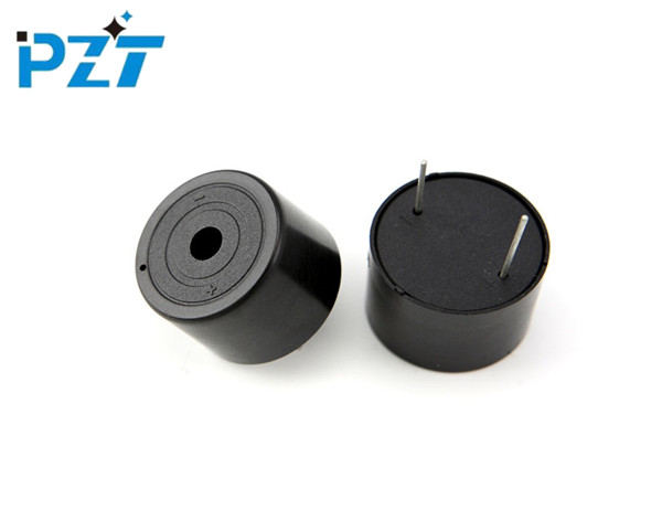
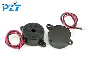
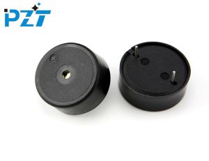
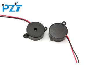
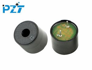
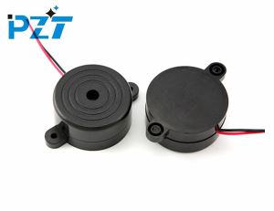
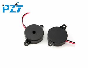
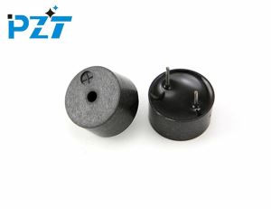
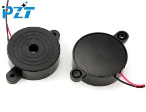
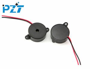
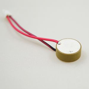
Piezoelectric Sounder
Model | LPB2418A-TB-12-2.8-15.0-R |
Rated Voltage | 12 VDC |
Operating Voltage | 3~20 VDC |
Current Consumption | =15 mA |
Test distance | 10 cm |
SPL | =90 dB @10cm |
Resonant Frequency | 2800±500 Hz |
Tone | Continuous sound |
Operating Temperature | -40 ~ +85 ? |
Storage Temperature | -40 ~ +90 ? |
Weight | 4.8 g |
Carton size | 66×36×29 cm |
Quantity | 2000 pcs |
Gross Weight | 11 Kg |
Audible short circuit tester
This is a very simple, low cost of formula audible continuity tester, it requires a quad comparator chip LM339 (IC1), and a piezoelectric buzzer several resistors can be easily made. Circuit power supply for the 9V battery. In fact, only one of the four comparators plays a major role. The other three comparators are connected to drive the mid-power piezo buzzer, PZ1.
Voltage divider formed by R1, R2 consisting of the inverted input of comparator A ? pin voltage is set at 190mV, and R3, R4 voltage divider set at a fixed voltage with the same 30mV input pin of ?. Resistor R5 is connected between the comparator A output and the noninverting input pin ? to provide the necessary feedback.
Reduce the triggering switch when the bouncing effect, the most effective solution is the introduction of a small amount of positive feedback hysteresis, the lag effect of the input voltage can be separated from the upper and lower hemispheric switching point, the circuit once the start of the switching process, the input voltage Before the reverse switching process must go through an important return trip, so that the input voltage pendulum and pendulum switch neatly.
In the standby state, since the potential of the inverting input pin ? (190mV) higher than the potential (30mV) ? noninverting input pin, so that the comparator output A is low, this low level to the comparator B, C, D trans Phase input pin, so that the output of the three comparators were high, so the voltage across the piezoelectric buzzer is almost equal. Buzzer does not sound.
Only when the resistance between two probes connected is less than 15O, the potential of the inverting input pin ? of comparator A can become lower than 30mV from 190mV. The polarity of the output of comparator A is reversed. Turn the output of the parallel comparators B, C, D low and the piezo buzzer to sound, indicating that the continuity between the probes is good. The three comparator outputs draw a total of 50mA, enough to make the piezo buzzer loudly.
With this tester can also determine whether the resistance is less than 15O resistance. If you wish to be larger or smaller than 15O, you can change the resistance of R1 ~ R4 to meet.
-
12 Volt Piezo Buzzer 5 Pieces / (Min. Order)
-
Piezo Beeper 5 Pieces / (Min. Order)
-
Piezo Buzzer With Wire Lead 5 Pieces / (Min. Order)
-
23mm Piezo Buzzer 5 Pieces / (Min. Order)
-
12v Buzzer Tweeter 5 Pieces / (Min. Order)
-
Piezo Sounder 5 Pieces / (Min. Order)
-
Piezo Alarm 5 Pieces / (Min. Order)
-
Piezoelectric Buzzer 5 Pieces / (Min. Order)
-
12v Piezo Buzzer 5 Pieces / (Min. Order)
 Favorites

-
 Piezo Alarm Buzzer
5 Pieces / (Min. Order)
Piezo Alarm Buzzer
5 Pieces / (Min. Order)
-
12 Volt Piezo Buzzer
5 Pieces / (Min. Order)
-
Piezo Beeper
5 Pieces / (Min. Order)
-
Piezo Buzzer With Wire Lead
5 Pieces / (Min. Order)
-
23mm Piezo Buzzer
5 Pieces / (Min. Order)
-
12v Buzzer Tweeter
5 Pieces / (Min. Order)
-
 24v Piezo Buzzer
5 Pieces / (Min. Order)
24v Piezo Buzzer
5 Pieces / (Min. Order)
-
Piezo Sounder
5 Pieces / (Min. Order)
-
Piezo Alarm
5 Pieces / (Min. Order)
-
Piezoelectric Buzzer
5 Pieces / (Min. Order)
-
12v Piezo Buzzer
5 Pieces / (Min. Order)
-
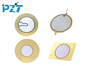 Piezo Disk
1 Pieces / (Min. Order)
Piezo Disk
1 Pieces / (Min. Order)
-
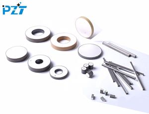 Piezoelectric Ceramics
1 Pieces / (Min. Order)
Piezoelectric Ceramics
1 Pieces / (Min. Order)
-
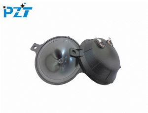 Piezo Tweeter
1 Pieces / (Min. Order)
Piezo Tweeter
1 Pieces / (Min. Order)
-
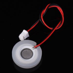 Piezo Atomizer Disc
1 Pieces / (Min. Order)
Piezo Atomizer Disc
1 Pieces / (Min. Order)
-
 Piezo Bender 27mm
1 Pieces / (Min. Order)
Piezo Bender 27mm
1 Pieces / (Min. Order)
-
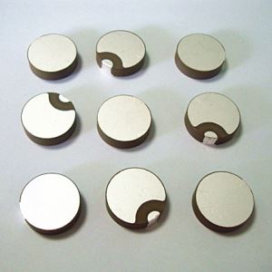 Piezoceramic Disc 1MHz
1 Pieces / (Min. Order)
Piezoceramic Disc 1MHz
1 Pieces / (Min. Order)
-
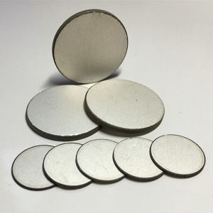 Piezoelectric Ceramic Disc
1 Pieces / (Min. Order)
Piezoelectric Ceramic Disc
1 Pieces / (Min. Order)
-
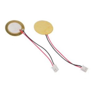
 Piezo Disc with Wire Leads
1 Pieces / (Min. Order)
Piezo Disc with Wire Leads
1 Pieces / (Min. Order)